
A while ago, I started a project to monitor power usage; you can read about it in my post Arduino: kWh Monitoring (part 1). Recently, I had a new “smart meter” installed, and naturally, I couldn’t let that go unnoticed.
A new smart meter means much more detailed monitoring. I asked the person installing it about the options, and they mentioned getting a dongle and being able to read the data on devices. I thought, “A dongle? We’ll see about that.” And so, I turned to my Arduino.
Dutch Smart Meter Requirements
The most interesting part of the smart meter is the P1 port—that’s where it’s all at. I searched for information on the P1 port and found the DSMR 4.0 standard. To my delight, people actually have a standard for connecting devices to meters, and they included the word “Dutch” in it. Goodbye, old-school infrared reflection detector! For some reason, the smart meter has “DSMR 4.2” written on it, which doesn’t matter much (apparently, there’s already a DSMR 5.0).
Build a DIY Serial Cable
To connect to the P1 port, I cut one end off a piece of 4-wire telephone cable and plugged it in. It was that easy. I connected one end to the Arduino breadboard, and Bob’s your uncle. The challenging part was understanding the inverted signal coming from the meter. I found that many people use USB serial cables, others use Raspberry Pi’s (which seems like overkill), and some use a transistor.
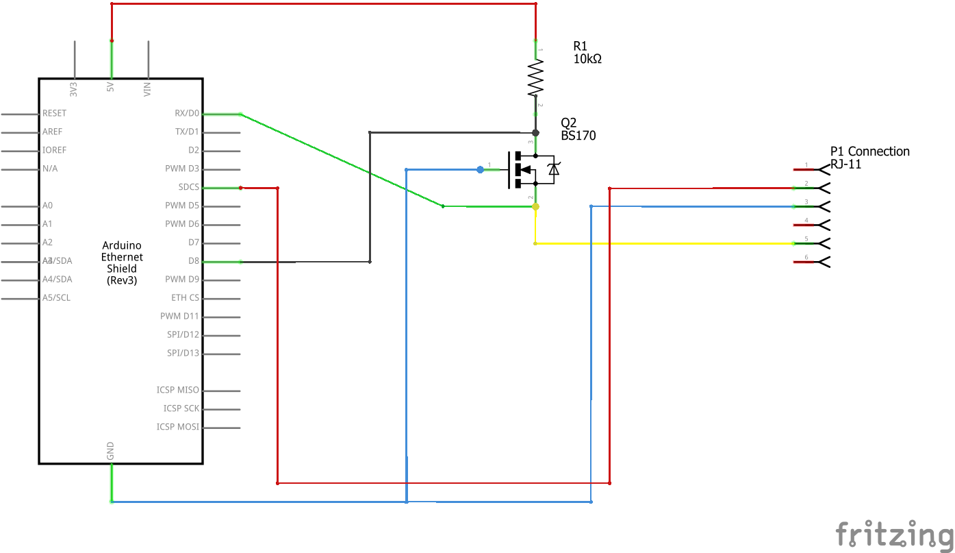
The last option caught my eye since it was inexpensive. I bought a BS170 transistor at the electronics store for a mere $1.50, connected it to a 10k resistor, and attempted to invert the signal. Despite my efforts, I couldn’t get any output from the meter. That is, until I combined the output into the Arduino D0 pin (labeled RX) and used the AltSoftSerial Library on pin 8—that’s when I had my eureka moment. (See my schematics below.)
I still don’t entirely understand why this works; I suspect it has something to do with the Arduino Library. If I disconnect pin 8 or pin 0, it stops working, so for now, I’m leaving them connected. I think this double connection might be causing some occasional strange or corrupt characters in the output. If you can explain what’s happening, I’m all ears—please leave a comment.
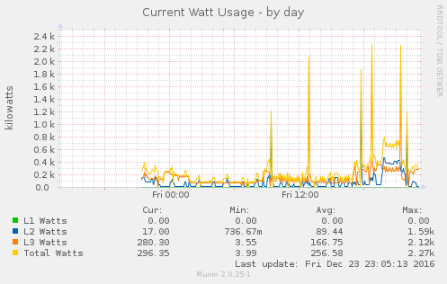
For those who prefer visuals, here’s a graph showing the output of all three phases from the meter.
The meter sends out a telegram every 10 seconds while the P1 port has power you can do this faster by just switching the P1 power on and off but who needs monitoring faster than every 10 seconds…
dependable Readings are more fun…
Fast forward to the present day, somewhere in 2023, and my setup has evolved quite a bit. I now have Home Assistant running on my Raspberry Pi, connected via a serial cable for increased dependability and longevity. This new configuration offers a more stable and long-lasting solution for monitoring my smart meter.
Thanks for reading, If you’ve got any idea’s to better this process let me know.
Leave a Reply